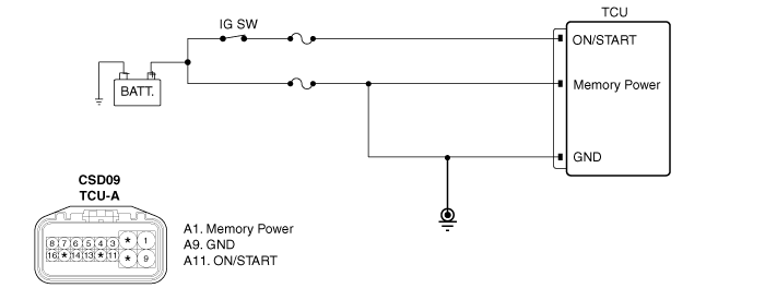
TCU check the Battery
voltage, in order to maintain optimum condition of each sensors and
solenoid-valve.
TCU set this code, when
input lower voltage than specified value.
Item
|
Detecting
Condition
|
Possible cause
|
DTC Strategy
|
| •
|
Check the voltage
range | |
|
Enable Conditions
|
|
Threshold Value
|
|
Diagnostic Time
|
| •
|
more than 20 times × more than1
sec | |
Fail Safe
|
| •
|
Self learning control is
inhibited |
| •
|
Adaptive control is
inhibited | |

| 1. |
Connect scantool to data link
connector(DLC). |
| 3. |
Monitor the "A/T RELAY VOLTAGE" parameter on
the scan tool.
Specification
: Battery voltage (Approx.
10~14V)
|

|
| 4. |
Is "A/T RELAY VOLT" within
specification?
|

|
▶ Go to "IG
Power inspection" procedure.
|
|

|
▶ Repair
"Fuse and Battery and relation part" as necessary and Go to
"Verification of Vehicle Repair"
procedure.
|
|
| 1. |
Engine "OFF" IG KEY
"ON". |
| 3. |
Measure the voltage between terminal of "IG
power" and chassis ground.
Specification
: Battery voltage (Approx.
10~14V)
| |
| 4. |
Is "VOLTAGE" within
specification?
|

|
▶ Go to "IG
ground inspection" procedure.
|
|

|
▶ Repair
"Fuse and Battery and relation part" as necessary and Go to
"Verification of Vehicle Repair"
procedure.
|
|
IG Ground Inspection
| 1. |
Engine "OFF" IG KEY
"ON". |
| 3. |
Perform the continuity test between "IG power"
terminal and chassis ground.
Specification
: Not continuity
| |
| 4. |
Is resistance within
specifications?
|

|
▶ Go to
"Battery power Inspection" procedure.
|
|

|
▶ Repair
"Fuse and Battery and relation part" as necessary and Go to
"Verification of Vehicle Repair"
procedure.
|
|
2. Battery Power Inspection
| 1. |
Engine "OFF" IG KEY
"ON". |
| 3. |
Measure the voltage between Battery power(B+)
terminal of wiring harness and ground terminal.
Specification
: Battery voltage (Approx.
10~14V)
| |
| 4. |
Is "VOLTAGE " within
specification?
|

|
▶ Go to
"Battery ground inspection1" procedure.
|
|

|
▶ Repair
"Fuse and Battery and relation part" as necessary and Go to
"Verification of Vehicle Repair"
procedure.
|
|
Battery Ground Inspection 1
| 1. |
Engine "OFF" IG KEY
"ON". |
| 3. |
Measure the voltage between Battery power(B+)
terminal of wiring harness and chassis ground.
Specification
: Battery voltage (Approx.
10~14V)
| |
| 4. |
Is "VOLTAGE" within
specification?
|

|
▶ Go to
"Battery ground inspection 2" procedure.
|
|

|
▶ Repair
"Fuse and Battery and relation part" as necessary and Go to
"Verification of Vehicle Repair"
procedure.
|
|
Battery Ground Inspection 2
| 1. |
Engine "OFF" IG KEY
"ON". |
| 3. |
Perform the continuity test between "Ground"
terminal of wiring harness side and chassis ground.
Specification
: Continuity
| |
| 4. |
Is resistance within
specifications?
|

|
▶ Fault is
intermittent caused by poor contact in the sensor's and/or
TCM(PCM)'s connector or was repaired and TCM(PCM) memory was
not cleared. Thoroughly check connectors for looseness, poor
connection, bending, corrosion, contamination, deterioration
or damage. Repair or replace as necessary and go to
"Verification of Vehicle Repair" procedure.
|
|

|
▶ Repair
"Fuse and Battery and relation part" as necessary and Go to
"Verification of Vehicle Repair"
procedure.
|
|
| Verification of Vehicle
Repair |
After a repair, it is
essential to verify that the fault has been corrected.
| 1. |
Connect scan tool and select "Diagnostic
Trouble Codes(DTCs)" mode |
| 2. |
Using a scantool, Clear
DTC. |
| 3. |
Operate the vehicle within DTC Enable
conditions in General information. |
| 4. |
Are you DTCs present?
|

|
▶ Go to the
applicable troubleshooting procedure.
|
|

|
▶ System
performing to specification at this
time.
|
|