
The Mass Air Flow Sensor
(MAFS) is located between the air cleaner assembly and the throttle body.
The MAFS uses a hot film type sensing element to measure the mass of
intake air entering the engine. This hot film type air flow sensor
consists of a hot film sensor, housing and metering ducts. Mass air flow
rate is measured by detection of heat transfer from a hot film probe. The
change in air flow rate causes change in the amount of heat being
transferred from the hot film probe surface to the air. A large amount of
intake air represents acceleration or high load conditions while a small
amount of intake air represents deceleration or idle. The mass of intake
air should increase at acceleration and be stable during constant engine
speed. The PCM uses this information to determine the injection duration
and ignition timing for the desired air/fuel ratio.
If PCM detects that
frequency signal of MAFS is lower than1000 Hz for more than 75 second
during one dignostic test(125 second) while enable condition is met PCM
determines that a fault exists and a DTC is stored.MIL(Malfunction
Indication Lamp) turns on when the malfunction lasts till consecutive 2
driving cycle.
Item
|
Detecting
Condition
|
Possible cause
|
DTC
Strategy
|
| •
|
Compares the airmeter input frequency to
a low limit | |
| •
|
Open or short in
harness |
|
Enable
Conditions
|
| •
|
Engine Running Time ≥ 5
second |
|
Threshold
value
|
| •
|
MAF frequency signal <
1000Hz | |
Diagnosis
Time
|
| •
|
Continuous
(More than 75 second failure for every
125 second tests ) | |
MIL On
Condition
|
|
Air Flow (kg/h)
|
Frequency (Hz)
|
12.6
|
2617.0
|
18.0
|
2958.0
|
23.4
|
3241.0
|
32.4
|
3653.0
|
43.2
|
4024.0
|
57.6
|
4399.0
|
72.0
|
4704.0
|
108.0
|
5329.0
|
144.0
|
5897.0
|
198.0
|
6553.0
|
270.0
|
7240.0
|
360.0
|
7957.0
|
486.0
|
8738.0
|
666.0
|
9644.0
|
900.0
|
10590.0
|

| 1. |
Check DTC Status
| (1) |
Connect scantool to Data Link
Connector(DLC). |
| (3) |
Select "DTC" button, and then Press "DTC
Status" to check DTC's information from the DTCs
menu. |
| (4) |
Read "DTC Status"
parameter.

|
| (5) |
Is parameter displayed "Present
fault"?
|

|
▶ Go
to "Terminal and connector inspection"
procedure.
|
|

|
▶
Fault is intermittent caused by poor contact in the
sensor's and/or PCM's connector or was repaired and PCM
memory was not cleared. Thoroughly check connectors for
looseness, poor connection, ending, corrosion,
contamination, deterioration, or damage. Repair or
replace as necessary and go to "Verification of Vehicle
Repair"
procedure.
|
| |
| Terminal And Connector
Inspection |
| 1. |
Many malfunctions in the electrical system are
caused by poor harness and terminal condition. Faults can also be
caused by interference from other electrical systems, and mechanical
or chemical damage. |
| 2. |
Thoroughly check connectors for looseness,
poor connection, bending, corrosion, contamination, deterioration,
or damage. |
| 3. |
Has a problem been found?
|
|
▶ Repair as
necessary and go to "Verification of Vehicle Repair"
procedure
|
|
|
▶ Go to "
Power Circuit Inspection "
procedure.
|
|
■ Check Voltage
| 1. |
IG "OFF" and Disconnect MAFS
connector. |
| 3. |
Measure voltage between power terminal of MAFS
harness connector and chassis ground.
|
| 4. |
Is the measured voltage within specification
?
|
|
▶ Go to
"Signal Circuit Inspection" Procedure.
|
|
|
▶ Check
fuse between MAFS and main relay is open or not
installed.
▶ Repair open in power
harness between MAFS and main relay and go to "Verification of
Vehicle Repair"
procedure.
|
|
| Signal Circuit
Inspection |
■ Check Voltage
| 1. |
IG "OFF" and disconnect MAFS
connector. |
| 3. |
Measure voltage between signal terminal of
MAFS harness connector and chassis ground.
Specification
: Approx. 5V
| |
| 4. |
Is the measured voltage within specification
?
|
|
▶ Go to
"Ground circuit inspection" procedure.
|
|
|
▶ If the
measured voltage is "0", go to "Check open in harness" as
follows. If the measured voltage is over "5V", go to " Check
short to battery in harness" as
follows.
|
|
■ Check Short To Battery In Harness
| 1. |
IG "OFF" and disconnect MAFS and PCM
connector. |
| 2. |
Measure resistance between signal and power
terminals of MAFS harness
connector. |
| 3. |
Measure resistance between signal terminal of
MAFS harness connector and signal terminal of IATS harness
connector.
|
| 4. |
Is the measured resistance within
specification ?
|
|
▶ Go to
"Check short to ground in harness" as
follows.
|
|
|
▶ Repair
short to battery in harness and go to "Verification of Vehicle
Repair"
procedure.
|
|
■ Check Short To Ground In Harness
| 1. |
IG "OFF" and disconnect MAFS and PCM
connector. |
| 2. |
Measure resistance between signal terminal of
MAFS harness connector and chassis ground.
|
| 3. |
Is the measured resistance within
specification ?
|
|
▶ Go to
"Check open in harness" as follows.
|
|
|
▶ Repair
short to ground in harness and go to "Verification of Vehicle
Repair"
procedure.
|
|
■ Check Open In Harness
| 1. |
IG "OFF" and disconnect MAFS and PCM
connector. |
| 2. |
Measure resistance between signal terminal of
MAFS harness connector and MAFS signal terminal of PCM harness
connector.
Specification
: Approx. below
1Ω.
| |
| 3. |
Is the measured resistance within
specification ?
|
|
▶ Go to
"Ground circuit Inspection" procedure.
|
|
|
▶ Repair
open in harness and go to "Verification of Vehicle Repair"
procedure.
|
|
| Ground Circuit
Inspection |
■ Check Open In Harness
| 1. |
IG "OFF" and disconnect MAFS connector and
then IG "ON". |
| 2. |
Measure voltage between signal terminal of
MAFS harness connector and chassis ground (Measurement
"A") |
| 3. |
Measure voltage between signal and ground
terminals of MAFS harness connector (Measurement "B")
Specification
: Voltage difference between
Measurement "A" and "B" is below 200mV.
| |
| 4. |
Is the measured voltage within specification
?
|
|
▶ Go to
"Component Inspection" procedure.
|
|
|
▶ Repair
contact resistance or open in harnesss and then go to
"Verification of Vehicle Repair"
procedure.
|
|
| 1. |
Visual Inspection
| (1) |
Check that MAFS is damaged, contaminated
or deformed. |
| (2) |
Has a problem been found ?
|
|
▶
Repair or replace as necessary and then go to
"Verification of Vehicle Repair"
procedure.
|
|
|
▶ Go
to "Check MAFS" as
follows
|
| |
| 2. |
Check MAFS
| (1) |
IG "OFF" and install a
scantool |
| (2) |
ENG "ON" and monitor "MAFS" data on the
service data. |
| (3) |
Monitor signal waveform at signal
terminal of MAFS with scantool.
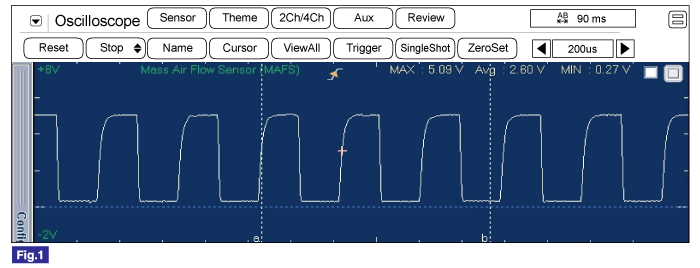
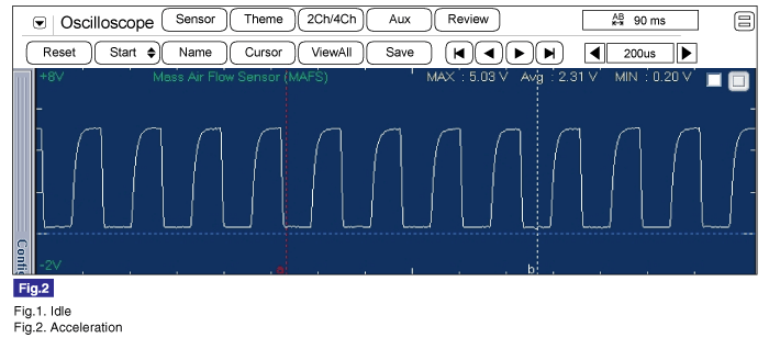
Specification : Signal waveform will be displayed as follows.
(Be aware that the signal of MAFS is not voltage display
but frequency display.)
|
|
| (4) |
Are both service data and signalwave
form dispayed correctly ?
|
|
▶
Substitute with a known - good PCM and check for proper
operation. If the problem is corrected, replace PCM and
go to "Verification of Vehicle Repair"
procedure.
There is a memory reset function on scantool
that can erase optional parts automatically detected and
memorized by PCM. Before or after testing PCM on the
vehicle, use this function to reuse the PCM on the
others.
|
|
|
▶
Substitute with a known - good MAFS and check for proper
operation. If the problem is corrected, replace MAFS and
go to "Verification of Vehicle Repair"
procedure.
|
| |
| Verification Of Vehicle
Repair |
After a repair, it is
essential to verify that the fault has been corrected.
| 1. |
Connect scantool and select "DTC"
button. |
| 2. |
Press "DTC Status" button and confirm that
"DTC Readiness Flag" indicates "Completed". If not, drive the
vehicle within conditions noted in the freeze frame data or enable
conditions |
| 3. |
Read "DTC Status"
parameter |
| 4. |
Is parameter displayed "History(Not Present)
fault"?
|
|
▶ System
performing to specification at this time. Clear the
DTC
|
|
|
▶ Go to the
applicable troubleshooting
procedure.
|
|